AP5-4-INV
Electric Design and Motor Characteristic Analysis of large capacity fully-HTS induction motor
*Satoshi Fukui1, Jun Ogawa1, Masakiyo Nakano1, Taiki Netsu1
- Niigata University1
Emissions from aviation and shipping have recently been increasing at a faster rate than for other transportation such as road vehicles and trains. As emerging countermeasures against requirements for carbon reduction in these transport sectors, various researches on electric propulsion systems are intensively being conducted [1], [2]. Particularly in the use of electric motors for aircraft propulsion system, there is severe requirement against power-weight ratio. It is considered that to meet this requirement of power-weight ratio is very difficult by the extension of conventional motor technologies. With recent progress of fabricating technology of long length and high current density high temperature superconducting (HTS) wires, their application to windings of rotating machines actually comes in sight [3]. Therefore, development of HTS motors with high power and light weight is expected to overcome the technical limit of conventional motors. The induction motor with HTS squirrel cage rotor (HTS-IM) has distinctive characteristics such as the synchronous speed drive by trapping magnetic flux in the HTS cage and the high power density due to the high current density in the HTS cage conductors [4]. Furthermore, the low AC loss and high current capacity HTS cable technology promising for AC applications is recently being developing [5]. By applying it to the armature winding, it is also expected that much higher power density can be achieved. In this study, we focused on the application of fully HTS-IMs to the large aircraft propulsion system and investigated the electromagnetic design to increase the power density.
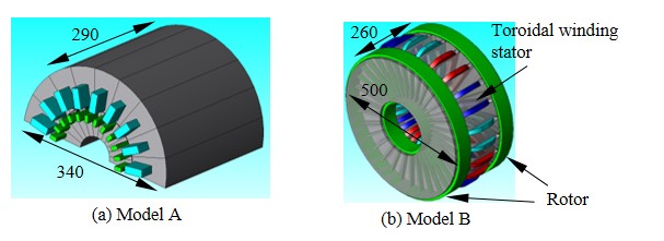
As examples, two types (a radial gap type and an axial gap type) were studied. The first model (model A) is a 3 MW-class fully HTS-IM with the radial gap structure (Fig. 1(a)). The rated voltage and current are 2 kV and 2 kA respectively. The synchronous speed and stator frequency are 6000 min-1 and 100 Hz (2 poles). The slot combination is 18 / 24 (stator / rotor). The average current density of stator slot is set at 60 A/mm2. The rotor bars consist of bundle conductor of HTS tapes and Cu bar. The ferromagnetic cores are used to reduce the magnetomotive force of the stator and to efficiently generate the magnetic flux. The detailed specification and geometry were designed by using the FEM analysis. The second model (model B) is a 5 MW-class HTS-IM with the axial gap structure (Fig. 1(b)). In this model, the toroidal winding stator is adopted. The toroidal winding stator is beneficial for the HTS conductor, since the sine-wave-distribution of magnetomotive force can be provided with simple rectangle coils. Two rotors with radially bars are arranged on both sides of the toroidal stator. It is considered that this double rotor arrangement is effective to increase power density, since the mechanical output can be generated from both sides of the stator. The synchronous speed and stator frequency are 6000 min-1 and 200 Hz (4 poles). The slot combination is 24 / 34 (stator / rotor). The average current density of stator slot is set at 50 A/mm2. The rated magnetomotive force of the stator HTS coil is 20000 ATpeak. The rotor bar is also the composite conductor of HTS tapes and Cu bar. The ferromagnetic cores are also used.
The numerical simulations in the no-load and lock-rotor conditions were conducted by the FEM analysis and the equivalent circuit parameters were obtained. The basic motor characteristics were analyzed by using the equivalent circuit for the HTS-IM introducing the nonlinear voltage-current characteristics of HTS. Based on the equivalent circuit analysis, it was confirmed that the designed HTS-IM models satisfy the performance of 3-5 MW-calss output power. In the presentation, the detailed design specifications of the HTS-IM models are summarized and the motor characteristics were reported.
References
[1] IATA : Aircraft Technology Roadmap to 2050, 2019.
[2] H. Kifune, M. K. Zadeh, “Overview of Electric Ship Propulsion and Fuel Consumption”, J. JIME, Vol. 54, No. 4, pp.95-100, 2019.
[3] K. S Haran, S. Kalsi, T. Arndt, H. Karmaker, R. Badcock, B. Buckley, T. Haugan, M. Izumi, D. Loder, J. W. Bray, P. Masson, E. W. Stautner, “High power density superconducting rotating machines—development status and technology roadmap”, Supercond. Sci. Technol. Vol. 30, 123002, 2017.
[4] T. Nakamura, Y. Itoh, M. Yoshikawa, T. Nishimura, T. Ogasa, N. Amemiya, Y. Ohashi, S. Fukui, M. Furuse, “Tremendous Enhancement of Torque Density in HTS Induction/Synchronous Machine for Transportation Equipments”, IEEE Trans. Appl. Supercond., Vol. 25, No. 3, 5202304, 2015.
[5] Y. Li , D. H. Kim, S. Inoue, Y. Yoshida, T. Machi, N. Amemiya, “Coupling Time Constant Measurements of Spirally-Twisted Striated Coated Conductors With Finite Transverse Conductance Between Filaments”, IEEE Trans. Appl. Super., Vol. 30, No. 4, 4703005, 2020.
Fig. 1 Numerical models.
Keywords: HTS Induction Motor
