ED5-5
Operation of a 4-bit RSFQ digital-to-analog converter based on a binary split-confluence configuration
*Naonori Sega1, Yuta Somei1, Hiroshi Shimada1, Yoshinao Mizugaki1
- The University of Electro-Communications1
RSFQ Circuitry is an attractive digital technology because it has great advantage to high-speed operation with low power consumption. In addition, high-precision voltage generation is its unique feature. Recently out group operated several kinds of RSFQ digital-to-analog converters (DACs) which weredesigned for application to the future AC voltage standard. One of them was the RSFQ-DAC based on the Σ-SBS (Sum of Selected Binary Sequence) configuration, where the input SFQ pulses was split into binary sequences and the selected SFQ binary sequences were merged at confluence buffers(CBs) in the output line [1]. Although our first test of a 6-bit Σ-SBS DAC operated correctly at low speed, its maximum operation frequency did not reach 1 GHz, whereas numerical simulation predicted correct operation at 11 GHz. In this paper, we present our new design and test results of a Σ-SBS DAC of 4-bit resolution. The maximum operation frequency is evaluated.
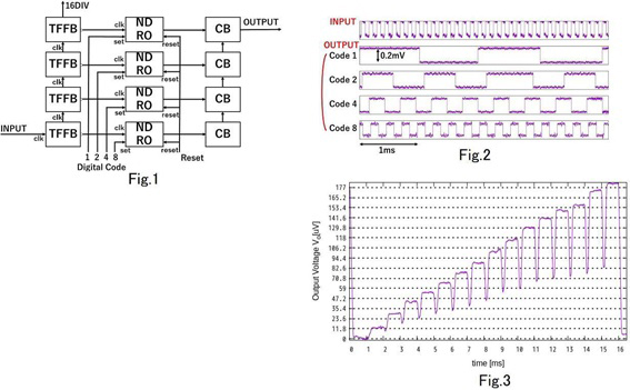
Fig. 1 shows a schematic of the 4-bit Σ-SBS DAC. The input SFQ signals of repetition frequency fin are divided into four periods (fin/2, fin/4, fin/8, and fin/16) through four stages of toggle flip-flops (TFFs). On the other hand, the digital input data are stored in the nondestructive readout memory cells (NDROs), which allow/prohibit SFQ signals split at TFFs to proceed into the output line according to the stored data of “1”/”0”. Finally, the SFQ signals passing through the NDROs are combined at CBs, and then, the output SFQ frequency is determined as∑4i=1 Difin/2n where Di is the stored data in the i-th NDRO. That is, the average output voltage of 16 levels from 0 to 15/16Φ0fin is realized.
We fabricated a 4-bit Σ-SBS DAC using the Nb 10 kA/cm2 process (referred to as HSTP) at National Institute of Advanced Industrial Science and Technology (AIST), Japan. In measurements, a test chip was cooled in liquid helium. Fig. 2 shows examples of measurement results for low-speed SFQ pulses. The input SFQ pulses were fed through a dc/SFQ converter, whereas the output signals were obtained via an SFQ/dc converter. We confirmed that the output signal was modulated by changing the digital input data to the NDROs. The results for the digital input codes of 1, 2, 4, and 8 are presented in Fig. 2, where the output frequencies are fin/16, 2fin/16, 4fin/16, and 8fin/16, respectively. (fin = 16 kHz.)Fig. 3 shows the result of a (1/16)-kHz sawtooth-like wave synthesis using high-speed input SFQ pulses generated by an over-biased Josephson junction. The average voltage across the over-biased Josephson junction was 189 μV, of which the corresponding Josephson frequency was 91.3 GHz. The digital input code was updated every 1 ms from 0 to 15. It is confirmed in Fig. 3 that 15 levels of the output voltage were realized, although there was non-negligible difference between the ideal and experimental voltage values.
Keywords: RSFQ, DAC
